LED Display acceptance inspection checklist.pdf
This standard specifies the technical requirements, inspection items, inspection methods, and acceptance criteria for the acceptance inspection of LED displays after installation. It is applicable to the acceptance inspection of indoor and outdoor LED display systems (including display cabinets/modules, control systems, power supply systems, and auxiliary equipment) after installation and commissioning.
The following documents are indispensable for the application of this standard. For dated references, only the versions with the indicated dates are applicable to this standard. For undated references, the latest versions (including all amendments) are applicable.
- Relevant national standards on electrical safety (e.g., standards for grounding resistance, power supply voltage stability)
- Industry standards for LED display performance (e.g., standards for brightness, color accuracy, and pixel defect rate)
- Wind load and seismic resistance design standards for building exterior decoration projects
- Manufacturer's technical specifications and system connection diagrams for the LED display
The basic unit of the LED display, consisting of LED lamp beads, driving circuits, and a structural shell, which is used to form the entire display screen through splicing.
The control unit of the LED display system, responsible for receiving, processing, and transmitting display signals, and controlling the operation of the display screen.
A display defect of the LED display, characterized by the presence of continuously lit or dark small squares (pixels or pixel groups) on the display screen, which affects the integrity and clarity of the displayed image.
Equipment used to reduce the operating temperature of the LED display (such as fans, heat sinks, and air conditioning systems), preventing component damage due to overheating.
4.1 The installation of the LED display shall comply with the manufacturer's design drawings and technical requirements, as well as relevant national and industry standards.4.2 All components of the LED display (including display cabinets/modules, Brain Box, power supply, and connecting cables) shall be free of quality defects such as damage, corrosion, or deformation, and shall have valid quality certificates.4.3 Before the acceptance inspection, the installation unit shall complete the commissioning of the LED display system, ensure that all functions are operating normally, and provide inspection records and technical data (such as system connection diagrams, commissioning reports, and component qualification certificates).
5.1.1 Damage Check: Visually inspect the surface of the LED display cabinet/module. There shall be no scratches, cracks, dents, or other mechanical damage; the coating shall be uniform and free of peeling or fading.5.1.2 Surface Evenness: Use a straightedge (length not less than 1m) and a feeler gauge to measure the surface evenness of the spliced display screen. The allowable deviation shall be within ±1mm.
5.2.1 Wind and Seismic Resistance: Verify that the installation structure (such as brackets, frames) has passed the design verification of wind load and seismic resistance, and meets the requirements of relevant national/industry standards (e.g., wind load resistance grade not lower than the local basic wind pressure requirement, seismic resistance grade consistent with the building's seismic grade).5.2.2 Screw Torque: Use a torque wrench to check the torque of the connecting screws (including cabinet splicing screws, structure fixing screws). The torque value shall be within the range of 15 ~ 20 Nm, and there shall be no looseness.
5.3.1 Equipment Installation: Check the installation position, quantity, and connection status of heat dissipation equipment (e.g., fans, heat sinks) in accordance with the manufacturer's technical requirements. The equipment shall be firmly installed, with no loose parts.5.3.2 Function Test: Start the heat dissipation system, and use a temperature detector to monitor the operating temperature of the LED display (measure the temperature of the cabinet surface and key components such as driving boards). The temperature shall not exceed the maximum allowable operating temperature specified by the manufacturer (generally not higher than 45°C for indoor displays, and not higher than 55°C for outdoor displays).
5.4.1 Visually inspect the exterior of the display screen, including the surface of the cabinet/module, the edges of the splicing seams, and the surrounding areas of the connectors. There shall be no debris such as glue residues, foam fragments, oil stains, or dust accumulation.5.4.2 For outdoor displays, check the surface of the protective glass (if equipped) to ensure it is clean and free of stains that affect display effects.
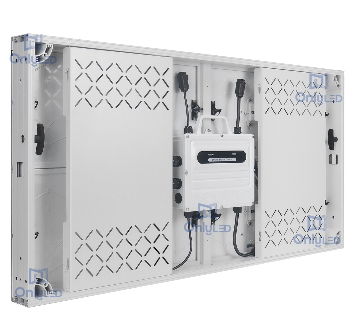
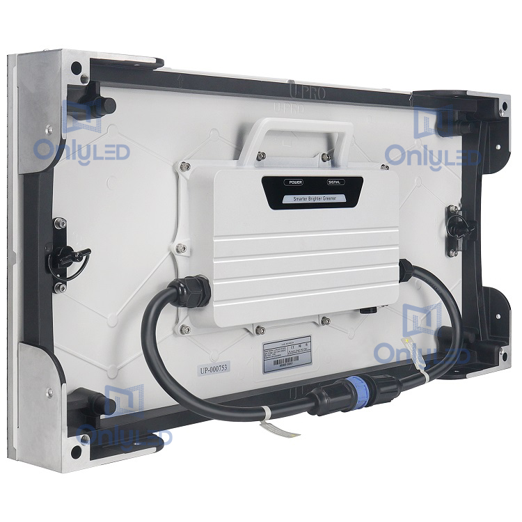
6.1.1 Signal and Power Line Connection: Compare the actual connection of signal lines (e.g., data cables, control cables) and power lines with the manufacturer's provided system connection diagram. The connection path, terminal wiring, and polarity shall be consistent with the diagram, with no wrong connections or missing connections.6.1.2 Brain Box Orientation: Check the installation orientation of the Brain Box. It shall be installed in the direction indicated by the manufacturer (usually with the marked side facing upward), and shall not be installed horizontally or inverted.
6.2.1 Grounding Connection: Check the grounding wire of the display system (including the cabinet, power supply, and Brain Box). The grounding wire shall be firmly connected to the dedicated grounding terminal, with no looseness or virtual connection.6.2.2 Grounding Resistance Test: Use a grounding resistance tester to measure the grounding resistance of the system. The grounding resistance shall not exceed 4Ω (in accordance with national electrical safety standards).
6.3.1 Voltage and Current Test: Use a multimeter to measure the input voltage and operating current of the LED display power supply. The voltage shall be within the rated voltage range specified by the manufacturer (e.g., AC 220V ± 10% for indoor displays, AC 380V ± 10% for large outdoor displays), and the current shall not exceed the maximum rated current of the power supply.6.3.2 Power Supply Stability: During the continuous operation of the display screen (not less than 2 hours), monitor the power supply voltage in real time. The voltage fluctuation shall not exceed ±5% of the rated voltage, and there shall be no power failure or voltage surge.
6.4.1 Waterproof Seal Installation: For outdoor displays or displays used in humid environments, check the waterproof seals at cable connection points (e.g., power line inlet, signal line interface). The seals shall be correctly installed, fully fitted, and free of gaps or damage.6.4.2 Connector Tightening: Check the tightening status of power line and signal line connectors. All connectors shall be tightened in accordance with the manufacturer's requirements (e.g., using a wrench to tighten threaded connectors to the specified torque), to prevent water ingress.6.4.3 Waterproof Test (for Outdoor Displays): Conduct a simulated rain test (using a water spray gun with a water pressure of 0.3 ~ 0.5 MPa, spraying at a distance of 1 ~ 1.5m from the display screen for 30 minutes). After the test, check the interior of the cabinet and connectors for water accumulation; there shall be no water ingress.
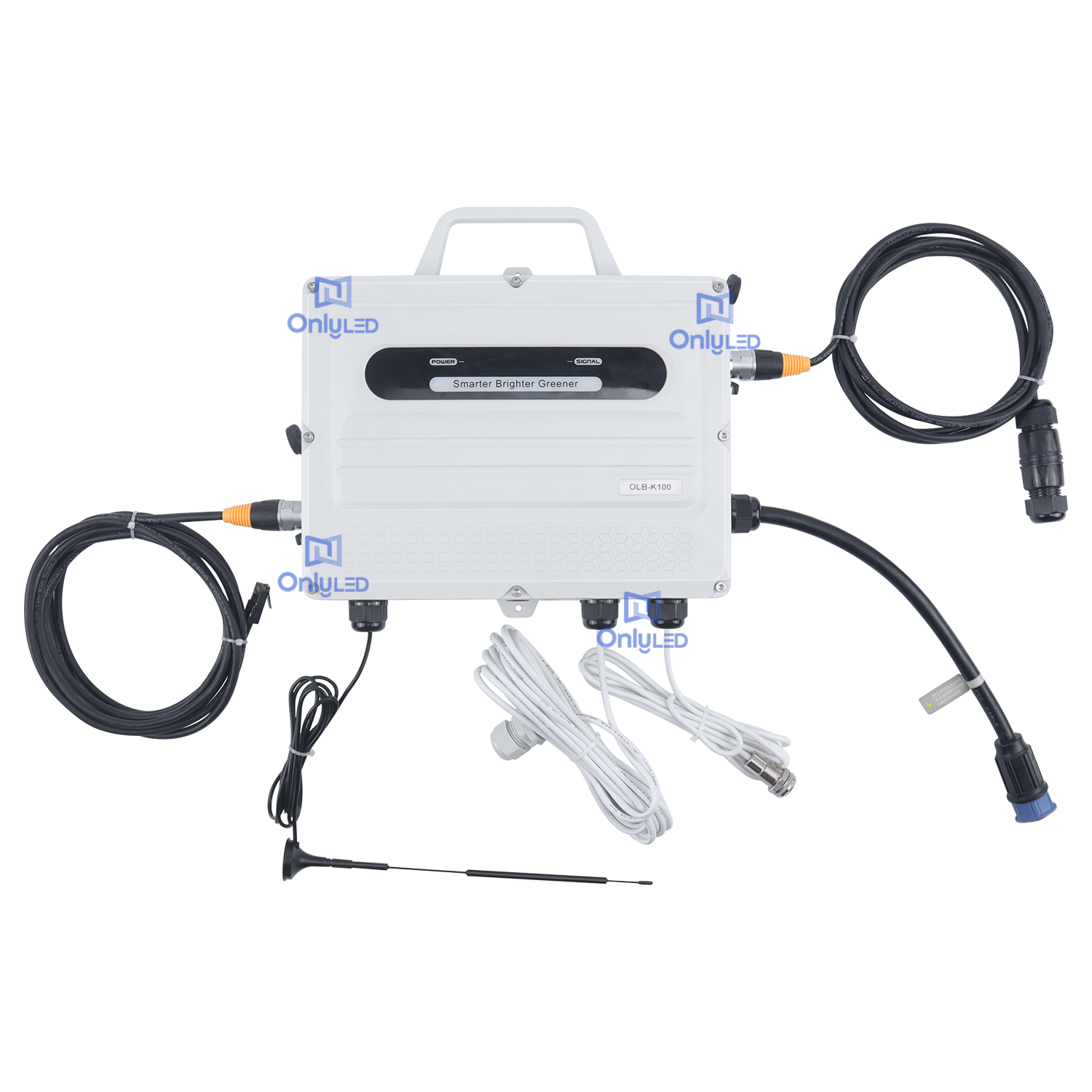
6.5.1 Orientation Recheck: Confirm again that the Brain Box is installed in the correct orientation (marked side upward), with no horizontal or inverted installation.6.5.2 Antenna and Sensor Installation: If the Brain Box is equipped with antennas (e.g., wireless communication antennas) or sensors (e.g., temperature sensors), check their installation. Antennas shall be installed vertically and firmly, with no obstruction; sensors shall be installed in the specified position (e.g., near the heat dissipation area) and connected correctly.6.5.3 Brain Box Function: Power on the Brain Box, check the indicator lights (e.g., power indicator, communication indicator). The indicator lights shall be in the normal state specified by the manufacturer (e.g., power indicator on, communication indicator flashing normally).
6.6.1 Waterproof Sealing Cap Installation: Check the end connectors of signal lines and power lines (including unused connectors). All end connectors shall be sealed with dedicated waterproof sealing caps. The sealing caps shall be tightly fitted, with no gaps, to ensure the stability of signal and power transmission and prevent water or dust ingress.6.6.2 Transmission Test: For connected end connectors, conduct a signal/power transmission test. There shall be no signal interruption, power loss, or abnormal voltage drop at the connectors.
7.1.1 Playback Quality: Load test programs (including text, images, and videos) into the display system. Visually inspect the playback effect: the content shall be clear and complete, with no blurring, ghosting, or color distortion; the color consistency of the entire display screen shall be good, with no obvious color differences between different areas.7.1.2 Flicker Check: Use a stroboscope to detect the display screen during playback. The flicker frequency shall meet the manufacturer's requirements (generally not less than 120Hz), and there shall be no visible flicker to the naked eye.7.1.3 Program Size Matching: Check whether the resolution and aspect ratio of the played program match the actual resolution and aspect ratio of the LED display. There shall be no stretching, compression, or cropping of the program content.
7.2.1 Defect Detection: Load a full-white, full-black, and full-primary-color (red, green, blue) test image into the display screen. Inspect the entire display screen pixel by pixel (or use a dedicated pixel detector) to check for mosaic phenomena (continuously lit or dark small squares).7.2.2 Defect Rate Requirement: The number of dead pixels (including bright dead pixels and dark dead pixels) shall not exceed the manufacturer's specified limit (generally, the single-point dead pixel rate shall be ≤ 0.0001, and the cluster dead pixel rate (≥ 2 adjacent dead pixels) shall be 0).
7.3.1 Sensor Installation: If the display system is equipped with a brightness sensor, check the installation position of the sensor. It shall be installed in an area not blocked by obstacles (e.g., no shelter above the sensor) and facing the direction that can accurately detect the ambient light intensity.7.3.2 Brightness Adjustment Test:
- Manually adjust the brightness of the display screen through the control system. The brightness shall change smoothly within the adjustable range (e.g., 100 ~ 2000 nits for outdoor displays), with no sudden changes or brightness jumps.
- Conduct an automatic brightness adjustment test: change the ambient light intensity (e.g., use a dimming lamp to simulate day and night light conditions). The display screen shall automatically adjust the brightness according to the ambient light changes, and the adjustment response time shall not exceed 5 seconds.7.3.3 Brightness Uniformity: Use a brightness meter to measure the brightness of multiple points (at least 9 points, evenly distributed) on the display screen. The brightness uniformity (minimum brightness/maximum brightness) shall not be less than 0.8.
7.4.1 Transmission Method Confirmation: Confirm the communication method used by the display system (e.g., wired Ethernet, wireless WiFi, 4G/5G). Check the connection status of the communication module (e.g., network cable insertion, wireless signal strength).7.4.2 Program Transmission Test:
- Transmit test programs (with a file size not less than 100MB) from the control computer to the Brain Box through the communication system. Record the transmission time and check the integrity of the received program (compare the file hash value before and after transmission; the values shall be consistent).
- Conduct a continuous transmission test (transmit 5 consecutive test programs). There shall be no transmission failure, packet loss, or program corruption.7.4.3 Remote Control Test (if applicable): If the system supports remote control, use the remote control device (e.g., mobile app, remote controller) to send control commands (e.g., turn on/off, adjust brightness, switch programs). The display screen shall respond correctly to the commands, with a response time not exceeding 3 seconds.
8.1 All inspection items specified in this standard shall be inspected one by one.8.2 For inspection items with quantitative indicators (e.g., surface evenness, grounding resistance, dead pixel rate), if the actual test results meet or exceed the requirements of this standard, the item is judged as "qualified"; otherwise, it is "unqualified".8.3 For inspection items with qualitative requirements (e.g., no damage, correct connection, no flicker), if there is no defect or non-compliance, the item is judged as "qualified"; otherwise, it is "unqualified".8.4 The LED display is judged as "qualified for acceptance" only if all inspection items are qualified. If there are unqualified items, the installation unit shall rectify the defects within the specified time (generally not more than 7 working days), and re-inspect after rectification. If the re-inspection results are all qualified, it can be judged as "qualified for acceptance"; if the re-inspection still has unqualified items, it is judged as "unqualified for acceptance".
9.1 The inspection unit shall fill in the "LED Display Acceptance Inspection Record Form" (see Appendix A) in detail during the inspection, including inspection items, test data, inspection results, and the signatures of the inspector and the person in charge of the installation unit.9.2 After the acceptance is qualified, the following documents shall be compiled into the acceptance file and archived by the relevant parties (e.g., the owner, the installation unit):
- This acceptance inspection standard
- LED display acceptance inspection record form
- Manufacturer's technical documents (system connection diagram, product manual, quality certificate)
- Installation and commissioning report of the LED display
- Rectification records (if any) and re-inspection reports