Company News
Step-by-Step Installation Guide for 10ft×20ft Pole-Mounted Digital LED Billboard (OnlyLED U-PRO-L Series) – 48Sheet Billboard Compatible
Manual download here:
![]() U-PRO-L Pole mounted LED display installation manual V1.pdf
U-PRO-L Pole mounted LED display installation manual V1.pdf
LED BILLBOARD WIRING LAYOUT DOWNLOAD HERE, AND ELECTRICAL REQUIREMENT FOR 10X20FT OUTDOOR DIGITAL LED BILLBOARD
![]() OL20230601W1-UP-L-4W4H-SmartPC.pdf
OL20230601W1-UP-L-4W4H-SmartPC.pdf
In the era of digital outdoor advertising, digital LED billboards have become a dominant medium for visual communication, offering unmatched brightness, dynamic display capability, and visibility across all weather conditions. Among the most popular configurations in global outdoor media is the 10ft × 20ft digital LED billboard, which corresponds to the 48Sheet billboard standard commonly used for highway, roadside, and urban digital signage.
To help contractors, engineers, and system integrators achieve a professional, safe, and reliable installation, ONLY LED DISPLAY has developed this comprehensive guide.
This article provides a complete step-by-step installation process for building a 10ft×20ft pole-mounted digital LED billboard, ensuring structural safety, electrical reliability, waterproof protection, and excellent image performance.“outdoor digital LED display,” “10x20ft digital LED billboard,” “48Sheet LED display,” and “pole-mounted digital LED billboard”

Overview: Why Choose the OnlyLED U-PRO-L Series for 10x20ft Digital LED Billboards
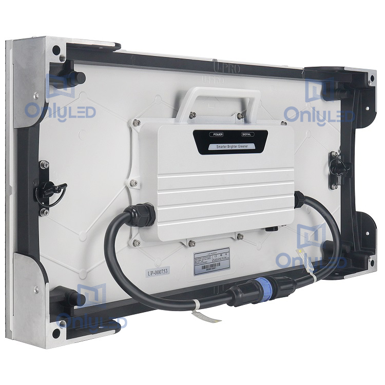
The OnlyLED U-PRO-L Series represents a new generation of outdoor LED display panels designed for professional billboard applications. Each cabinet is built using aluminum alloy housing for superior heat dissipation and long-term weather resistance, making it ideal for outdoor environments such as highways, parking lots, commercial zones, and public information displays.
Core Advantages of the U-PRO-L Series
High Brightness and Energy Efficiency: Each cabinet features a high-brightness LED module with common-cathode power design, ensuring optimal energy efficiency while maintaining vivid image quality under direct sunlight.
Excellent Weather Resistance: IP65-rated protection ensures that the screen operates stably even under heavy rain or dust exposure.
Modular Design: The 2ft × 4ft cabinet dimension allows flexible combinations—perfect for constructing standard American-sized digital billboards, including 10ft×20ft configurations.
ETL and CE EMC Certified: The U-PRO-L series complies with international safety and electromagnetic standards, ensuring suitability for European and North American markets.
Easy Maintenance: Front and rear service options, quick-swap modules, and waterproof connectors reduce maintenance time and increase installation efficiency.
When correctly installed following this guide, the OnlyLED U-PRO-L 10x20ft outdoor digital LED display provides stable operation, seamless visuals, and an impressive service life—making it a trusted choice for outdoor advertising companies, city infrastructure projects, and media owners.

Pre-Installation Preparation: Laying the Foundation
1. Site Selection and Structural Requirements
Before beginning any installation, confirm that the installation site meets the structural and safety requirements for a pole-mounted digital LED billboard.
Pole Foundation Construction:
Use C30-grade concrete, as indicated in the U-PRO-L Installation Manual. The foundation should be deep and wide enough to bear the combined weight of the steel structure, LED panels, and supporting electronics. For a 10ft×20ft LED billboard comprising 25 U-PRO-L cabinets (2’×4’ each), the total structure weight can exceed 800 kg, requiring reinforced anchoring bolts and wind-load resistance.Wind and Seismic Resistance:
Structural engineers must calculate local wind loads and seismic conditions. The foundation should be designed to resist strong gusts and prevent tilting of the pole or screen assembly.Maintenance Space:
Leave a minimum 80cm clearance around the pole and structure. This space is crucial for access during inspections and maintenance.Pre-Fabricated Steel Frame:
Assemble the frame horizontally on level ground before lifting. Check the verticality and flatness with a spirit level. Any deviation will lead to visible misalignment in the display surface once the LED cabinets are installed.
2. Tools and Materials Preparation
For a successful and efficient installation, prepare the following tools and materials as specified in the manuals:
Essential Tools
| Tool Name | Application |
|---|---|
| Electric screwdriver with S6 hex bit | Fastening M8×50 bolts between cabinets and structure |
| Hex wrenches (L-type and T-type) | Cabinet assembly/disassembly |
| No.14 open-end wrench | Tightening nuts on the support structure |
| Hand drill (21N·m torque) | Drilling and fixing connecting plates |
| Multimeter | Detecting short circuits and verifying voltage stability |
Core Installation Materials
U-PRO-L LED cabinets: 25 pcs (2’×4’)
LED modules: factory-calibrated modules matching the cabinet model
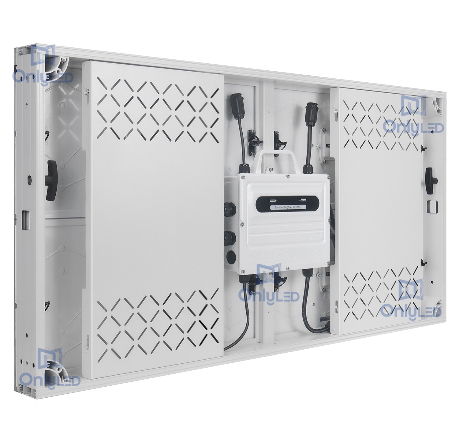
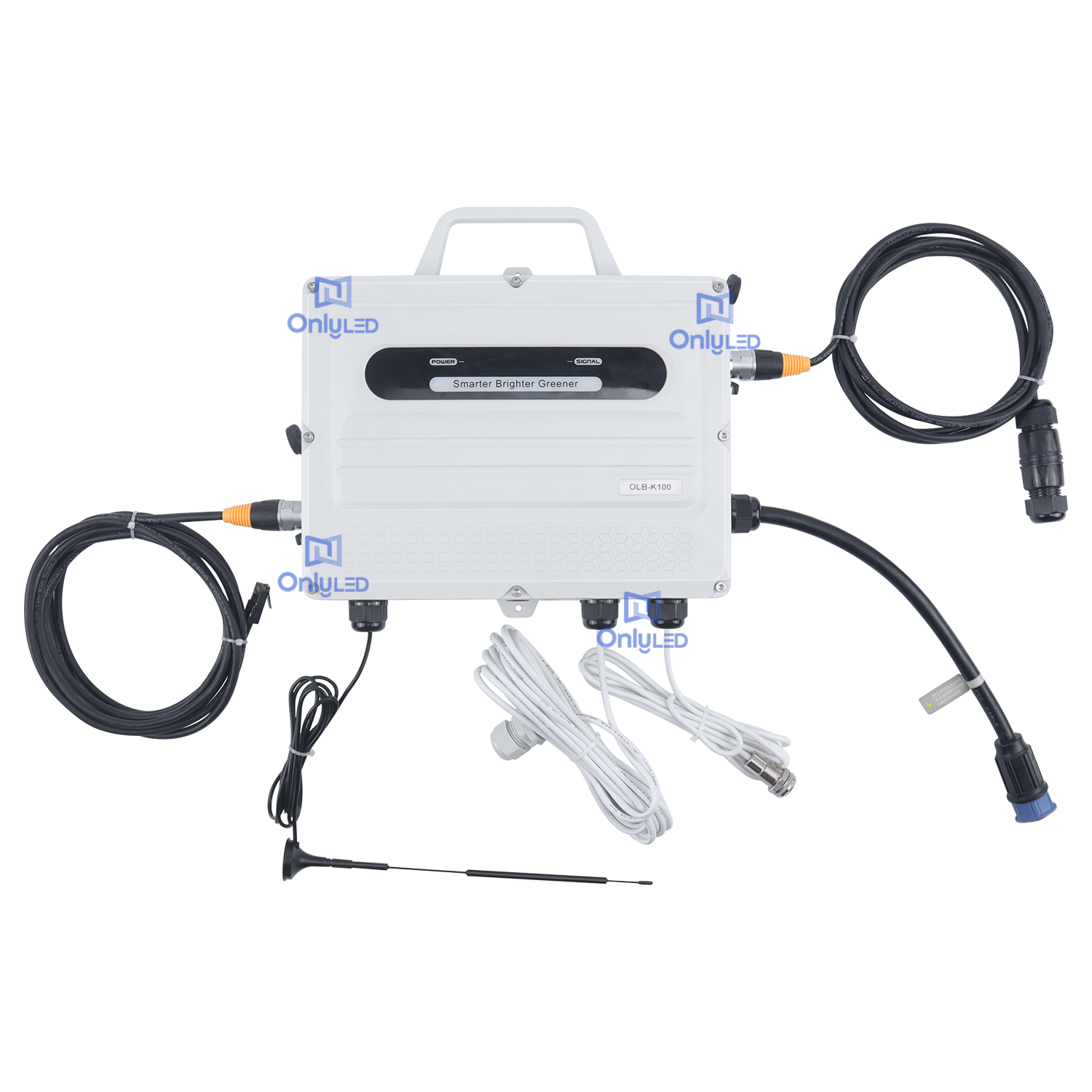
Control system: 2 NOVASTAR OLB-N1 controller boxes (Brain Boxes), 2 receiving cards, 2 HUB cards, 4G antennas
Power components: 1 main power distribution box, 2 backup power units
Cabling and connectors: 3-wire power cables, 9-core signal cables, aviation network cables, waterproof connectors, male/female end caps
Mounting hardware: M8×50 screws (117+ pcs), M8 nuts, connecting plates, and sealing accessories
All components should be checked against the packing list provided with the U-PRO-L manual before proceeding.
3. Parts Inspection and Quality Verification
Unpacking Safety:
Open all crates and packaging boxes on a soft surface. Never place LED panels face-down to avoid pressure damage to the LED lamp beads.
Visual and Electrical Inspection:
Verify the surface flatness of each cabinet is within ±1mm.
Check that waterproof rubber rings in all connectors are intact and flexible.
Inspect power and signal cables for signs of wear or fraying.
Confirm all labeling matches the system wiring diagram from OL20230601W1-UP-L-4W4H-SmartPC.pdf.

Installation Process: Step-by-Step Construction
Step 1: Steel Structure Assembly
Align the pre-fabricated steel frame with the pole’s base flange and anchor it using M32×1000 bolts. Tighten to the specified torque and ensure the structure is perfectly vertical.
Pro Tip:
Draw reference alignment lines on the frame before lifting to simplify cabinet alignment later. Double-check all welding seams for full penetration and strength to prevent future deformation.
Step 2: Cabinet Installation (Bottom to Top)
Follow the numbering sequence of the U-PRO-L cabinets to ensure proper order and signal continuity.
Start from the bottom row: Install the first row completely before proceeding upward.
Check levelness after each row: Use a spirit level and keep deviation within 1mm.
Fasten securely: Use an L-shaped wrench and tighten all M8×50 screws (torque: 15–20Nm).
Reinforce stability: Connect adjacent cabinets using connecting plates and M8-40 self-tapping screws.
Properly installed cabinets will form a seamless, flat LED surface, ensuring high visual quality for the entire 10×20ft digital LED billboard.
Step 3: Power and Signal Wiring
The power and data wiring layout must strictly follow OL20230601W1-UP-L-4W4H-SmartPC.pdf.
Power Wiring:
Use 3-wire power cables (black = live, white = neutral, green = ground).
Divide the total power into three independent circuits, each carrying less than 18A.
For 25 cabinets (540W each), total power ≈ 13,500W.
At 220V supply, total current = 13,500W ÷ 220V ≈ 61.4A, so each circuit ≈ 20.5A.Select 2.5mm² power cables to handle this load safely.
Seal all unused connectors with waterproof end caps.
Signal Wiring:
Use 9-core double-male cables to connect the NOVASTAR receiving cards in sequence.
Arrange both main and backup signal routes for redundancy—if one fails, the system remains operational.
Use aviation plug network cables (3m) between the controller box and the PC, secured with waterproof connectors to resist humidity.
This dual-path data design ensures signal stability and uninterrupted display performance—a critical requirement for professional outdoor digital LED billboards.
Step 4: Controller and Power Distribution Setup
Controller Installation (Brain Box):
Mount the OLB-N1 controller box vertically with the “UP” arrow facing upward.
Avoid horizontal or inverted mounting to prevent internal heat buildup.
Install the 4G antenna in an open area for stable wireless updates.
Position the temperature sensor away from direct heat sources for accurate readings.
Power Distribution Box Installation:
Calculate the total and circuit currents as defined in the manual.
Wiring color codes: green (ground) → black (live) → white (neutral).
Limit single-cable output to ≤18A.
Mount the box vertically and label all circuits for clear maintenance reference.
The control and power systems together form the central nervous system of the 10ft×20ft digital LED billboard, ensuring consistent power flow and stable data transmission.
Step 5: Pre-Lifting Safety Inspection
Before lifting the assembled display, perform a thorough inspection:
Structural Check: Verify that all bolts, welds, and connections are tight.
Electrical Test: Use a multimeter to confirm no short circuits exist in LN, NG, or LG lines.
Functional Test:
Power up the system using temporary power input.
Play a test video to confirm correct color calibration and no dead pixels.
Check brightness sensors: the screen should dim under strong sunlight and brighten automatically at dusk.
Passing all tests ensures the system’s readiness for pole mounting.
Step 6: Pole Mounting and Final Fixation
With professional lifting equipment, raise the assembled structure and secure it onto the pole.
Assign a trained technician to guide the alignment during lifting to avoid contact between the screen and pole.
After mounting:
Tighten all anchor bolts to the specified torque.
Connect the external power via waterproof PG connectors.
Ensure all cabinet back covers and distribution box lids are fully closed and sealed.
Recheck screen verticality and adjust if needed.
Step 7: Post-Installation Debugging and Acceptance
Thermal Management:
Ensure the display area has proper ventilation. If the edges are enclosed, use perforated aluminum sheets to promote airflow and avoid overheating.
Waterproof Test:
Simulate light rainfall with a water hose to check for leaks at connectors and end caps. Any sign of moisture must be resolved before operation.
Final Acceptance:
Use the “LED Display Acceptance Checklist” from the U-PRO-L manual. Inspect and verify:
Surface flatness and seamless splicing
Signal stability and color uniformity
Brightness response and temperature control
Waterproof integrity and cabinet fastening
Once all checkpoints are marked “√,” the 10x20ft pole-mounted digital LED billboard is officially ready for operation.
Safety and Maintenance Guidelines
1. Electrical Safety
Always disconnect the power supply before performing any maintenance. The distribution box operates at high voltage and can pose serious hazards if mishandled.
2. High-Altitude Work
During maintenance, technicians must wear certified safety belts and use stable scaffolding or hydraulic lifts. Never stand directly on the screen structure.
3. Routine Maintenance
Monthly inspections are recommended to ensure continued reliability:
Tighten all M8 bolts and structural joints.
Replace aging waterproof gaskets.
Clean LED module surfaces gently with anti-static brushes or soft cloths to maintain brightness and prevent dust accumulation.
4. Troubleshooting
If display abnormalities occur (e.g., blackout, flickering, or color issues):
Check the power distribution box first.
Inspect power cables and signal lines.
Review control software settings.
If the issue persists, contact OnlyLED Technical Support immediately.
+86-136-8251-1977
info@onlyled.com
Conclusion
This Step-by-Step Installation Guide is the result of OnlyLED’s 20 years of expertise in outdoor LED display engineering. It combines real-world experience with the technical precision found in U-PRO-L Installation Manual V1.pdf and OL20230601W1-UP-L-4W4H-SmartPC.pdf to help partners worldwide install 10ft×20ft pole-mounted digital LED billboards safely, efficiently, and professionally.
By adhering to these standards, users will benefit from:
Long-term reliability under all weather conditions
Brilliant visual performance that enhances advertising impact
Simplified maintenance and high operational uptime
Compatibility with 48Sheet billboard infrastructure
At ONLY LED DISPLAY, we are dedicated to building LED systems that are not only brighter and smarter but also greener and more energy-efficient—continuing our mission to illuminate the world responsibly.